

Next: Dark current
Up:
The
ALFOSC Camera
Previous: Quantum-efficiency
The CCD has hardware overscan regions of two columns at each end of
the serial register. These areas are somewhat too small for a high signal to
noise measurement and are suspected
to be affected by the illumination of the imaging area, so they are
not recommended as bias level reference.
The recommended type of ``extended'' overscan can only be used for read-out
windows
extending to the edge of the CCD opposite of the amplifier being used,
as it is generated by continued clocking and read-out after the last image
column.
Overscan in the X-direction is set by the ``xover'' command, and
in the Y-direction by ``yover''. The Y-overscan is of little practical
use, though.
To get the overscan region in the image, the window size must be
specified to go beyond the border of the CCD by the width of the overscan.
E.g. An image of the section [1500:2052,something] with a X-overscan width
of 50 using the A-amplifier would be defined like this:
ampl A
xover 50
xbeg 1500
xsiz 602 (i.e. 602 = 2052 + 50 - 1500)
And when using the B-amplifier, an image with overscan must begin at
x=1, e.g. for an image with 650 imaging pixels and 50 overscan pixels,
the set-up would be:
ampl B
xover 50
xbeg 1
xsiz 700
The default x-overscan size is 50 and zero in the y-direction.
Post-processing by BIAS will always make the x-overscan appear at the
right border of the image, whatever amplifier is specified.
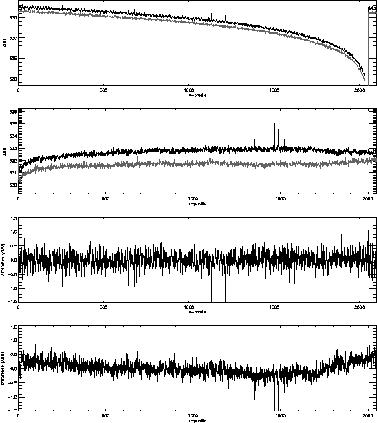
A comparison between two bias frames is shown in figure 11.
The two frames were separated by seven exposures, in all two hours apart.
An offset in the level between the two images of about 1 ADU is seen.
To minimize this, the temperature of the CCD and electronics should be kept
stable. By applying an offset based on the overscan level, the bias
drift can be corrected.
A strong gradient is present in the X-direction. As the gradient
reproduces well, it should not create problems. Amplifier B was used, making
the overscan region appear next to the region with the strong gradient.
In the Y-direction a bias level fluctuation of about 1 ADU amplitude is seen
during read-out. The variation is sufficiently slow to make tracking of
the variation using the extended overscan possible, making bias subtraction
to better than 1 ADU feasible.

Figure 11:
Structure of, and differences between two bias frames, made two hours
apart.
Amplifier B in high gain, mpp mode was used.
In the upper plot, the X-profiles of two bias frames are displayed.
A strong gradient is present, and the bias level has drifted about
1 ADU.
The ``extended'' overscan covers columns 2053 to 2102.
In the plot below, the Y-profiles are shown, and in the two plots at the
bottom, the differences between the profiles are shown with the global
drift subtracted.
In the X-direction, difference between the images is below detection level,
and the overscan tracks the bias level well.
In the Y-direction, which is the direction of the parallel shift, a bias
level drift during read-out is visible, with an amplitude of approx. 1 ADU.
By tracking the overscan level in the Y-direction, this structure can be
eliminated.
If the read-out window does not extend over the edge of the CCD, the extended
overscan will not be available.


Next: Dark current
Up:
The
ALFOSC Camera
Previous: Quantum-efficiency
Tim Abbott
Mon Apr 12 17:00:34 ACT 1999
