Commissioning of the spectroscopic mode of NOTcamNOTcam was designed such that grisms and slits can be mounted and rotated into the beam to quickly switch from imaging mode to spectroscopy and vice-versa. We have done extensive tests in order to prepare for the spectroscopic mode. The tests were followed by first-light observations in August 2003, for the low-res spectroscopic mode of NOTcam. Since then, this mode has been offered to the community.In May 2005, we obtained first-light observations for the medium-resolution spectroscopic mode of NOTcam. This mode can now also be applied for.
Nevertheless, further tests still remain to be done as part of the
ongoing commissioning of the spectroscopic mode of NOTcam. Action
points are indicated by a small dot, below.
In 2004 new copper slit holders were installed for the 128 and 64
micron slits, which made the deformations less apparent.
One of the 4 slits is clearly wrinkled because of the above effect,
but proves to be useful as the jaws remain quite parallel. Although
the slit width is 128 micron according to specifications, it is imaged
to about 2-2.5 pixels FWHM (instead of 4 pixels) on the detector by the
Wide-Field Camera of NOTcam. This slit is usable for point
sources.
Also for the HRC mode we have only one useful slit, and also here the
slit that was originally designed to be imaged onto 4 pixels, is
actually giving about 2.5-pixel resolution. This
plot shows the slit transfer function of the 44 micron slit,
again normalised such that the Y axis of the plot indicates the
effective slit width. The slit is suitable to be used for observations.
The grismSo far one grism has been designed by Michael Andersen, and this grism is installed in NOTCAM. The grism has an echelle grating and is designed to give intermediate resolution (2-pixel R=2500, with dispersion 2.5-4.1 Angstrom/pixel) in J (5th and 6th order), H (4th order) and K (3rd order) when used with the WFC. In combination with the HR Camera the resolution will be about 3 times higher, but the sampled wavelength range will be about 3 times less. The grism is used in combination with the JHK filter set in NOTcam. The grism was delivered in July 2003, and was mounted in a holder made by Niels Michaelsen in Copenhagen. This plot shows the throughput of the grism as measured by the manufacturer (note that the order overlap has not been accounted for).
With the grism in the beam the internal focus has to be upped by 200
units for the WF Camera (with respect to no grism).
In the end of 2004, the aperture wheel assembly was machined to allow
it to be moved 2mm away from the collimator (towards the sky). This
was needed to be able to focus aperture wheel items (e.g. slits, pinholes)
with the HRC. The tables below reflect the internal focus of WFC and
HRC slits, after the movement of the aperture wheel assembly.
It turned out that in order to be able to properly focus the
High-Resolution Camera, the aperture wheel assembly had to be moved
away from the collimator, and the slits have to be mounted in a
special holder such that they are as far away as possible from the
collimator. The only way to achieve the mounting of this holder was
to use one of the 4 big aperture wheel hole positions.
The slits for use with the WFC, however, needed to be positioned
further towards the collimator by about five millimeters (with aperture
wheel moved) in order to get proper focus over the full ZJHK wavelength
domain. The first-light observations were carried out in good seeing
conditions, and indicated that for the WFC spectra there is no clear
evidence for astigmatism caused by the positioning of the slits with
respect to the collimator.
For the HRC the on-sky measurements also show no evidence that
the displacement of the slit adversely affects the imaging quality.
Instrument flexureUsing the small pinhole and the WFC, flexure tests showed that slit-shifts of up to 4 pixels can be expected when slewing to different sources at high airmass for random rotator angles. While keeping the rotator angle fixed, e.g. following one source using the parallactic angle, the slit shifts are usually less than 1 pixel. For the parallactic angle the shifts are mostly along the slit.These flexure slit-shifts are generally much larger than the shifts introduced by the (re)positioning of the aperture wheel. We have tested the repeatability of the slit position after moving the aperture wheel. We used the HR Camera with the telescope at zenith. Here, the slit ran parallel to the columns of the detector (Y direction), with the rotation of the aperture wheel introducing shifts in the X direction. Scatter between subsequent X-positions of the slit is about 0.1-0.2 HR pixels (0.01-0.02 arcsec), however sometimes a larger step of about 0.5 HR pixels occurs (0.04 arcsec). The large step may correspond to the motor of the aperture wheel losing track of 1 stepper motor unit. Considering the above there is no clear preferred direction for the slit, i.e. along detector columns or rows, as flexure-induced shifts are much more important than shifts introduced by the (re)positioning of the aperture wheel. It is clear that wavelength calibration frames will have to be obtained at each target position on the sky. Considering the detector cosmetics, we have decided that the preferred slit position is horizontal, such that the spectra run along the columns of the array. Note that for a horizontal slit the parallactic angle has TCS rot-pos = -90 or 90. For vertical slits: rot-pos = 0 or 180.
For the J-band exposure times on the order of 200 seconds do not give
suitable sky-lines with enough flux. For this purpose we have
experimented with calibration lamps normally used with ALFOSC. As
part of the experiment the ZnAr and Ne lamps were hung above NOTcam
at a distance similar to that of the flatfield lamp inside the
telescope baffle. Although these particular lamps do not emit useful
lines in H and K, they did provide lines with which the J band can be
calibrated.
As of 2005, we have a calibration unit in the telescope baffle, that
can be used for NOTCAM spectroscopy. In order to use the lamps, the
mirror-covers need to be closed, introducing extra overheads. The unit
contains a flatfield lamp that is also used for ALFOSC, and a Xenon
and Argon lamp. Currently the lamps can be switched on in the control
room manually. Arc maps can be found here.
Wavelength stabilityFor the first-light data in the H-band the wavelength solution was not stable: the dispersion changing by 0.25% between exposures taken 1 hour apart, but at similar sky position and rotator angle. Could be a small tilt of the grism on the order of 0.2 degree. Or else flexure within the camera. Or movement of the slit from/to collimator? Needs testing!During further tests it was noted that when moving the telescope the wavelength zeropoint and the dispersion can change on the 1% level, which effectively means that both wavelength calibration arc frames and fringe correction flats have to be obtained at each and every telescope pointing.
Flatfielding and fringesA flat field lamp is situated inside the telescope baffle. The lamp flats are a necessary means to get rid of the quite substantial pixel-to-pixel variations of the detector. From the first-light observations we found that one can achieve a signal to noise ratio of S/N=80 in the spectral continuum using standard reduction steps. The problem with the baffle lamp is that the mirror covers have to be closed in order for correct operation.Using the flatfield lamp inside the telescope baffle a clear ripple pattern becomes immediately present. These ripples are probably due to interference in the 330 micron thick sapphire detector substrate. The fringe wavelength is linear with wavelength of the incident light.
Fringe amplitudes are highest in the central parts of the array. The fringes are around 25% peak-to-peak when the HRC with the 44-micron slit is used (for the old engineering array !).
On dark frames, and frames with low count levels, such as the sky part
of spectroscopic images or on wavelength calibration images, hot rows
are clearly visible (see this
report or the first-light
report). The count level in the hot rows does note scale with
exposure time. In fact, the hot rows behave more like rows with a
deviant zero level.
The number of hot pixels increases with exposure time (see
table below).
For exposures of more than 5 to 10
minutes the hot pixels are so abundant that they may inhibit proper
reduction of the spectra. The number of hot pixels for long exposures
is similar when using either reset-read-read or ramp-sampling mode.
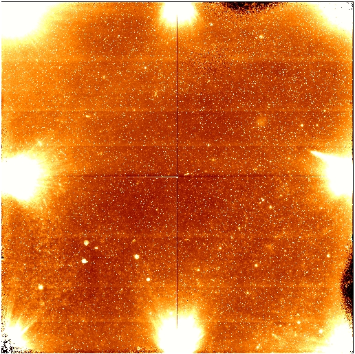
An unfortunate feature of the new science array is the presence of
clusters of hot pixels. In long dark exposures (see the 729 sec dark
expo below) these patches of hot pixels appear as stellar images:
In order to get optimal extraction to work, the 2D images first have
to be corrected using a bad-pixel map. Interpolation across bad pixels
provides the first rough correction that the optimal extraction
algorithm cannot handle. A bad-pixel map can easily be constructed
from two flat fields with different exposure levels. This map should
be (re-)made for each observing run. Even for very bright stars
variance weighting and cleaning of deviant pixels is worth doing.
The lamp flats are essential to get rid of the substantial
pixel-to-pixel variations of the detector, and should be obtained
after each telescope pointing.
Wavelength calibration data should be obtained after each telescope
pointing.
For the first-light WFC observations it was possible to correct for
telluric lines and at the same time for the fringes by using a nearby
featureless comparison star. The S/N in the continuum was around 80
after this correction.
For horizontal slits, the sky lines run along the rows of the
detector. For sky-line based wavelength calibration one needs to
extract these sky lines. The sky lines are bent because of optical
distortion, and run into bands of hot rows. It should be possible to
subtract out the hot rows using dark frames. Note that the counts in
the hot rows do not scale with exposure time of the dark frames.
The dark frames show different and non-linear background levels for
different exposure times. It is a good idea to obtain a set of dark
frames with the same exposure times as used for the science and other
calibration frames.
John Telting |
||||||||||||||||||||||||||||||||||||||||||||||||||||||||||||||||||||||||||||||||||||||||||||||||||||||||||
| ||||||||||||||||||||||||||||||||||||||||||||||||||||||||||||||||||||||||||||||||||||||||||||||||||||||||||
