FAPOL commisioning report
NOTE The default orientation of the Calcites has been changed in November 2008. The Calcites are now mounted "vertically" by default. I.e. the ordinary component is the lower one, the extraordinary component the upper one. The old setup ("Horizontal Mount", ordinary to the left, extraordinary to the right) is still available, but only if especially requested by the observers.
Imaging mode
Preliminary tests indicates that the transmissions of the 1/2
wave plate + calcite are about:
57 % in U
75 % in B
77 % in V
79 % in R
81 % in I
in comparison to the flux with the filter only. Most of the
attenuation is in the calcite plate.
Spectroscopic mode
Internal ALFOSC focus
Both images of the slitlet were found to be sharp with an internal
ALFOSC focus set to 850 (22/2-2007). The width of the so-called
1.8" slitlet was measured to be close to 1.5" (8 pixels).
With the internal focus at 850 the telescope focus for normal
imaging (no calcite, no retarder) was at 23130 (for no filter). The
focusing was done using the focus pyramid and the I-band filter and
correcting back the I filter offset.
Slit alignment
For spectropolarimetry it is very hard to get a perfect alignment
of the slit, since it has to be aligned with respect to the calcite
plate by eye. Currently, the slit is pretty well aligned with the
calcite, while the calcite is not entirely perfectly aligned with
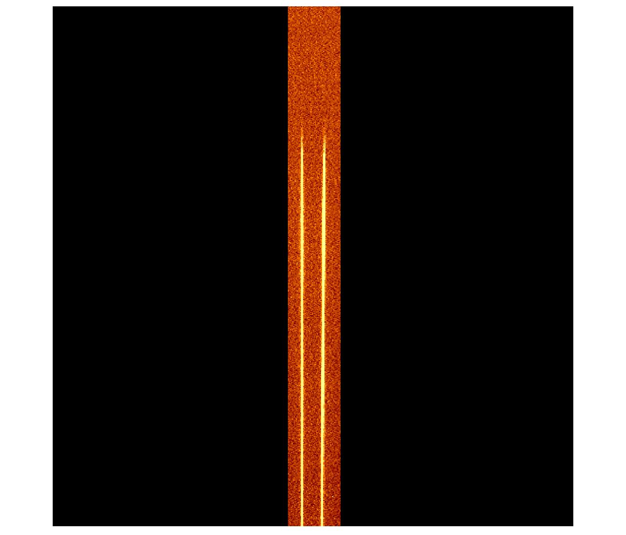
the CCD. The two images of the slit will therefore follow the lines
of the CCD, but one image of the slit is about 1 to 1.5 pixels
shifted relative to the other. This should be possible to calibrate
well with the arc lamp spectra.
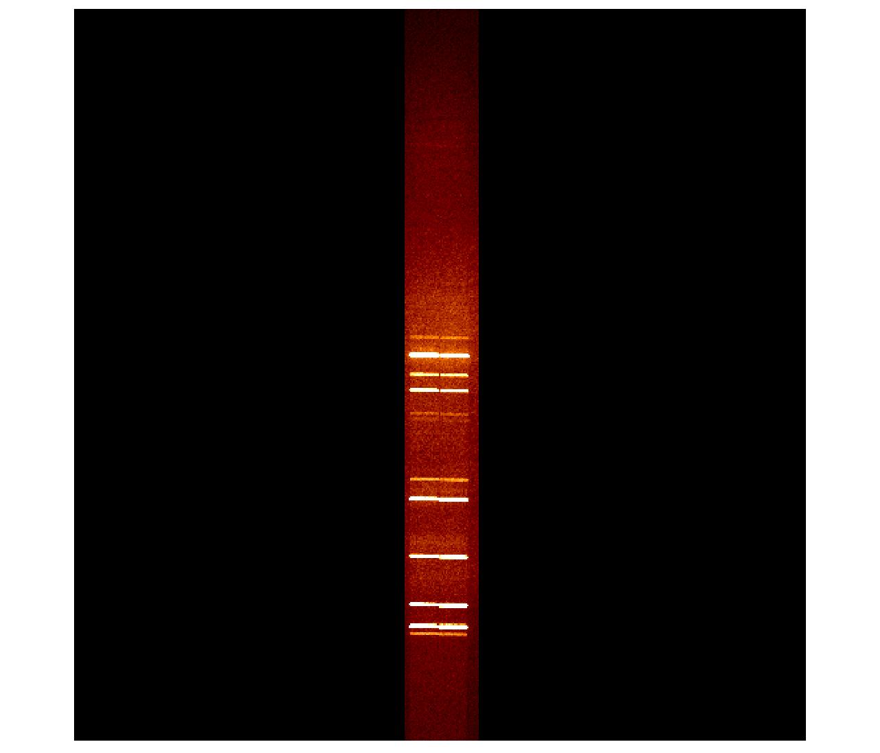
 This is an
example of the He arc lamp taken with Gr#6 and the 1.8" polarimetric
slitlet. This is an
example of the He arc lamp taken with Gr#6 and the 1.8" polarimetric
slitlet.
Calibration spectra
In order to take arc lamps you have
to take the retarder plate out of the beam, and then put in the
calibration lamp mirror and turn on the arc lamp.
For spectral flats the best solution is to use the blue halogen
lamp mounted on the inside of the baffle cover. Then the flats can
be taken in all orientations of the retarder plate - if wanted. We
have done this, but data reduction will show whether this is strictly
needed.
Dispersion in calcite
Because of the dispersion in the calcite, the ordinary component (left)
will have its spectrum well aligned along the columns of the CCD, while
the extraordinary component (right) will be slightly misaligned with
the separation between the two components the largest in the blue end
of the spectrum.

|
